COLE LEFEVER
L/E OPTION
LMI CORPORATE CENTER
ENGLEWOOD, CO


Click HERE to access PDF version of report...
PART I - GENERAL BUILDING DATA
General Building Data
Building Name | LMI Corporate Center
Location | Englewood, Colorado
Building Occupant | [Confidential]
Building Type | Office, Group B (Construction Classification Type II)
Size | 140,000 sq. ft.
Height | 60 ft. with 4-floors total, all above grade
Completed Date of Construction | September 15, 2016
Project Cost | $6,000,000 for tenant improvement
Project Delivery Method | Design-Assist
----------------------------------------------------------------------------------------------------------------------------------------------------------------------
Project Team
Owner | [Confidential]
Architect | RNL Design
General Contractor | Saunders Construction
Project Manager | JLL
Electrical/Lighting Engineer | AE Design
Mechanical/Plumbing Engineer | Maxson Engineering
----------------------------------------------------------------------------------------------------------------------------------------------------------------------
Architectural Design & Functional Components
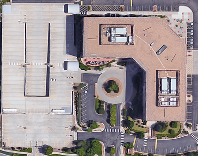
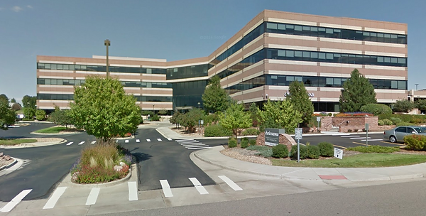
The LMI Corporate Center is an existing office type space that has been contracted under a new tenant. The purpose of the space is to provide and conduct quality business practices. The LMI Corporate Center features an on-site deli, landscaped common areas, serving and kitchen areas, on-site property management, and incredible mountain views. Additionally, the building has building and monument signage for larger users and men's and women's locker rooms with showers. The 140,000 square foot building was originally built in 1997 and is currently under renovations. The building shape is in the form of an L. One end of the building is referenced as the South Side or South Wing and the other side of the building is referenced as the West Side or West Wing.
----------------------------------------------------------------------------------------------------------------------------------------------------------------------
Codes In Effect
-
2015 International Building Code (IBC)
-
2014 National Electric Code (NEC)
-
2015 International Plumbing Code (IPC)
-
2015 International Mechanical Code (IMC)
-
2015 International Energy Conservation Code (IECC)
-
2012 International Energy Conservation Code for Lighting Compliance (IECC)
-
2015 International Existing Building Code (IEBC)
-
2009 ANSI (as referenced in the 2009 International Building Code)
----------------------------------------------------------------------------------------------------------------------------------------------------------------------
Zoning
City of Centennial Building Department Jurisdiction
----------------------------------------------------------------------------------------------------------------------------------------------------------------------
Historical Reference
Not Applicable (N/A)
----------------------------------------------------------------------------------------------------------------------------------------------------------------------
Building Envelope
Exterior Walls
- The exterior walls between each floor are constructed of EIFS material.
Exterior Windows & Doors
- The exterior windows/walls and doors are constructed of tempered glass glazing.
Roof Construction
- N/A from current Renovation Construction Documents.
----------------------------------------------------------------------------------------------------------------------------------------------------------------------
Sustainability Features
The LMI Corporate Center has an integrated fiber optic telecom conduit system designed to allow redundant dual feeds into the building and also provides a direct hardware link to all buildings within the campus. The building utilizes normal and emergency power distribution systems. Abundant power is available to users including redundancy provided by automatic transfer switches fed from two separate electrical substations. Curtain wall glazing on the exterior perimeter and interior glazing in select offices for natural lighting.
PART II - ENGINEERING SYSTEMS
Architecture + Construction
The LMI Corporate Center was originally built in 1997. It has currently undergone a full electrical and mechanical renovation which is why this building was chosen. The building was contracted under a Design-Assist project delivery method. The project was slated for completion on September 15, 2016. All prior and current construction complies with up to date code information. The renovation was estimated to cost around $15 million for all disciplines.
The project is not LEED certified, therefore none of the LEED accreditation will go into effect in this project.
As previously stated, the building is in the shape of an inverted “L” where one end of the building is referred to as the West Wing and the other end is referred to as the South Wing.
----------------------------------------------------------------------------------------------------------------------------------------------------------------------------------
Electrical
Xcel Energy is the primary utility company on site.
The building utilizes two (2) sources of power distribution.
-
Normal Power Distribution
-
Generator Power Distribution (Emergency & Critical Power)
-
Normal Power Distribution
-
Three-Phase incoming power from Xcel Energy to existing pad mounted transformer.
-
Size: 1500kVA
-
Secondary Voltage: 480/277V
-
Phase/Wire: 3φ, 4W
-
-
Transformer feeds the Main Service Distribution Switchboard (MSDS) located in the first floor electrical room.
-
Size: 5000A
-
Voltage: 480/277V
-
Phase/Wire: 3φ, 4W
-
AIC Rating: 65kAIC
-
Enclosure Type: NEMA 1
-
-
The MSDS then serves all normal high-voltage distribution panels (480/277V). The normal low-voltage distribution panels (208/120V) are fed from the normal high-voltage distribution panels which utilize step-down transformers from 480/277V to 208/120V. The MSDS also serves all mechanical equipment that is designed on the normal power distribution system. The three automatic transfer switches (ATS) are fed from the MSDS as well.
-
-
Generator Power Distribution (Emergency & Critical Power)
-
Two (2) Engine Generators (EG) feed the Engine Generator Paralleling Control Switchgear (EGP) which feeds the Main Engine Generator Distribution Switchboard (EGD).
-
Size(s): 1500KW (EG), 5000A (EGP & EGD)
-
Voltage: 480/277V
-
Phase/Wire: 3φ, 4W
-
-
The Main Engine Generator Distribution Switchboard (EGD) feeds three (3) separate Automatic Transfer Switches (ATS-#). They are labeled ATS-1, ATS-2, and ATS-3 respectively. Each ATS individually feeds an Additional Engine Generator Distribution Switchboard (EGD-#).
-
(i.e. ATS-1 feeds EGD-1, ATS-2 feeds EGD-2, ATS-3 feeds EGD-3)
-
Size(s): 1200A
-
Voltage: 480/277V
-
Phase/Wire: 3φ, 4W
-
-
EGD-1 feeds EGD-S (the emergency high-voltage distribution switchboard for the south side of the building). The emergency high-voltage distribution system utilizes step-down transformers from 480/277V to 208/120V to emergency low-voltage distribution panels for smaller loads on each floor. EGD-1 also feeds the emergency high-voltage distribution panels for larger loads on each floor. EGD-1 also feeds an Uninterruptible Power Supply (UPS-1). UPS-1 feeds Critical Distribution Board S (CD-S, critical high-voltage distribution switchboard for the south side of the building). The critical high-voltage distribution system utilizes step-down transformers from 480/277V to 208/120V to critical low-voltage distribution panels for smaller loads on each floor. Each floor is also equipped with an IDF Panelboard which are fed from the critical low-voltage distribution panels. EGD-1 is TVSS protected.
-
Size(s): 1200A (EGD-1), 400A (CD-S), 250A (EGD-S)
-
Voltage: 480/277V
-
Phase/Wire: 3φ, 4W
-
-
EGD-2 feeds EGD-W (the emergency high-voltage distribution switchboard for the west side of the building). The emergency high-voltage distribution system utilizes step-down transformers from 480/277V to 208/120V to emergency low-voltage distribution panels for smaller loads on each floor. EGD-2 also feeds the emergency high-voltage distribution panels for larger loads on each floor. EGD-2 also feeds an Uninterruptible Power Supply (UPS-2). UPS-2 feeds Critical Distribution Board W (CD-W, critical high-voltage distribution switchboard for the west side of the building). The critical high-voltage distribution system utilizes step-down transformers from 480/277V to 208/120V to critical low-voltage distribution panels for smaller loads on each floor. Each floor is also equipped with an IDF Panelboard which are fed from the critical low-voltage distribution panels. EGD-2 is TVSS protected.
-
Size(s): 1200A (EGD-2), 400A (CD-W), 250A (EGD-W)
-
Voltage: 480/277V
-
Phase/Wire: 3φ, 4W
-
-
EGD-3 feeds existing mechanical equipment. EGD-3 is not TVSS protected.
-
Size: 1000A (EGD-3)
-
Voltage: 480/277V
-
Phase/Wire: 3φ, 4W
-
-
----------------------------------------------------------------------------------------------------------------------------------------------------------------------------------
Lighting
All lighting throughout the building is to be LED fixtures in order to save on energy consumption of outdated lamp types, reduce the amount of maintenance required to keep the fixtures functional and to prolong the life of the intended design. Some fixtures utilize the low-voltage distribution of 120V and some utilize the high-voltage distribution of 277V. This is strictly based on the manufacturer’s ability to produce fixtures at either 120V, 277V or UNIVERSAL (which in case either voltage may be used).
Specialty and decorative fixtures are used throughout the building in common areas and areas of interest (i.e. main lobby, dining area, etc.). All lighting remote transformers, drivers, and power supplies for all fixtures are located in an accessible location for ease of maintenance.
The building utilizes lighting controls systems such as standardized toggle switches, synergy type digital switches, wall and ceiling mounted occupancy sensors, daylighting sensors in areas where abundant natural sunlight is available (i.e. along exterior walls), wall-stations with variable presets that are integrated with various lighting control relay panels organized by floor and wing of building (i.e. west or south). The lighting control relay panels are fed power via the electrical room on either side of the building (i.e. west or south).
----------------------------------------------------------------------------------------------------------------------------------------------------------------------------------
Mechanical
Package Variable Air Volume (VAV) roof-top units with gas heating and electric/ Direct-Expansion refrigerant cooling. Ductwork is distributed throughout the building to variable air volume units to provide zone control. Each zone has a space temperature sensor to allow for individual zone temperature adjustments. Fan powered VAV units are equipped with local electric heating coils at the units to provide additional zone heating.
Air cooled split systems are used to provide dedicated cooling in the IDF/MDF and telephone closets. These consist of an air-cooled roof-top condensing unit, refrigerating piping down the respective rooms, and fan-coil units are used to provide cooling only to rooms.
The restroom cores are provided with dedicated roof mounted exhaust fans to provide code required ventilation.
The building utilizes four (4) existing roof top units (RTU’s) with the capacity of supply 45,000 CFM per unit. RTU-1 & 2 ventilate floors one and two and RTU-3 & 4 ventilate floors three and four. Air is supplied and returned through the use of thermal and exhaust fans, fan coil units (FCU’s) and VAV boxes throughout the facility.
For cooling purposes, the building design integrates Air Cooled Condensing Units into the framework and well as Drycooler Units. Along with these cooling units, computer rooms throughout the site are conditioned via Computer Room Packaged Air Conditioning Units. For heating purposes, the building design integrates Water Source Heat Pumps into the frame work.
The mechanical design in this building also enhances the use of a Temperature Control Matrix which can be integrated into the BAS system. This allows for total control of all spaces conditioned via the Temperature Control Matrix.
----------------------------------------------------------------------------------------------------------------------------------------------------------------------------------
Structural
The structural framework for this building is existing since it was pre-built in 1997 and was recently under renovation. The existing structural system remained in place for the current renovations.
The existing structure is concrete encased steel vertical structural system with a pretension poured-in-place concrete slab decks as to support loading conditions designed by the structural engineer.
The exterior wall structure is composed of EIFS material, while most of the interior walls are constructed of either metal-stud gypsum wall board, glazing or a specialty type of material based on the space provided.
----------------------------------------------------------------------------------------------------------------------------------------------------------------------------------
Fire Protection
All new fire alarm devices shown shall tie into the existing building-wide fire alarm system. The contractor shall verify that the existing system has adequate capacity for the new devices shown, and provide new power supplies as necessary for a complete and operational system.
The contractor shall coordinate specific requirements to meet all current international building and fire codes as well as all amendments set for by centennial/south metro fire. Confirm with the local authority having jurisdiction prior to work commence.
The contractor is to warranty any new wiring and devices as part of their scope of work. The contractor will be responsible for a complete operation fire alarm system at time of project completion.
----------------------------------------------------------------------------------------------------------------------------------------------------------------------------------
Transportation
Public Elevators
Location: (3) in Main Lobby
Type: Existing (automatic operation)
Voltage: 480V
Phase: 3φ
Public Stairwells
Locations: (1) on West Side, (1) on South Side, (2) in Main Lobby
Type: Existing
----------------------------------------------------------------------------------------------------------------------------------------------------------------------------------
Telecommunication
Existing power/data zone boxes under raised floor from demolished furniture system is remaining and reused for the routing of cabling to the new furniture system.
A MDF (Main Distribution Frame) Room exists on the southern part of the first floor.
Each individual floor above has two (2) IDF (Intermediate Distribution Frame) Rooms, one on the south side of the building and the other on the west side of the building. Each room is connected and routed via the MDF Room on the first floor via a MTTB (Main Telephone Terminal Backboard).
----------------------------------------------------------------------------------------------------------------------------------------------------------------------------------